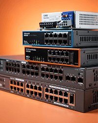
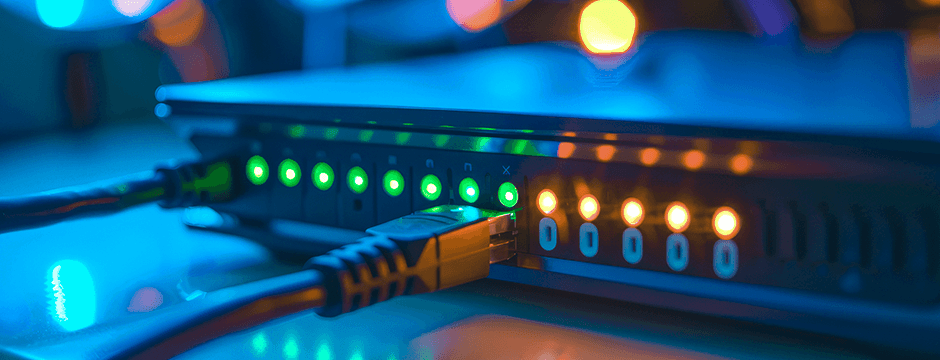
High-performance switches and networking solutions built for seamless connectivity, scalability, and long-term reliability, ensuring stable data transmission, advanced network control, and optimized performance across diverse applications.

Years Experience
Projects Completed


Global Clients
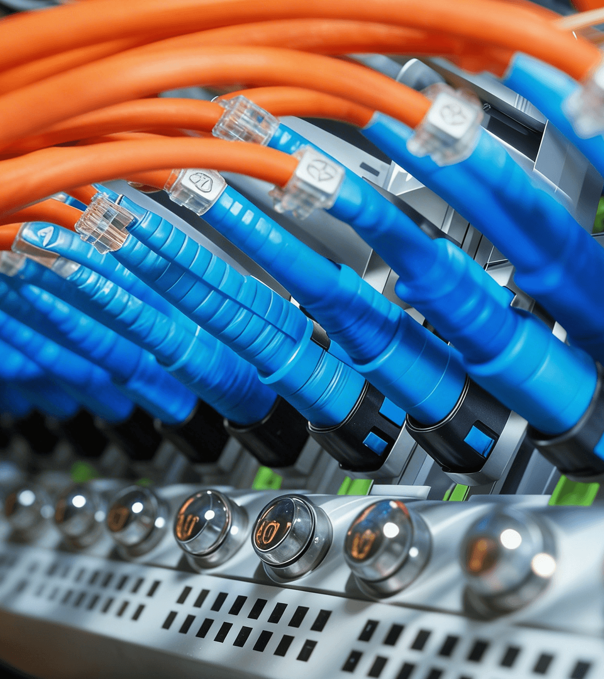
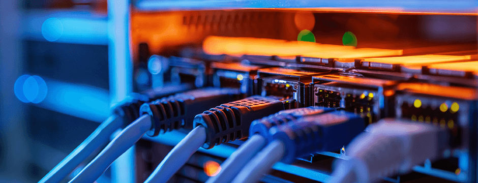
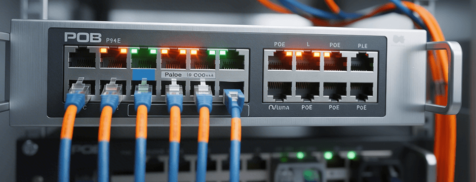
Power your CCTV, Wi-Fi, and industrial networks with robust PoE and industrial-grade switches engineered for demanding environments and uninterrupted performance—ensuring stable connectivity, efficient power delivery, and long-term reliability.
Years Experience
Projects Completed
Global Clients
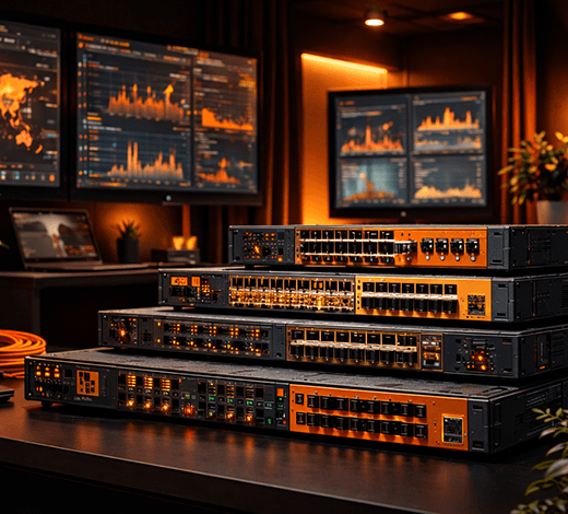
From enterprise networks to smart systems, Born Electronics provides scalable and future-ready solutions that keep your business connected, secure, and efficient—enabling seamless operations, improved performance, and long-term reliability.
Years Experience
Projects Completed
Global Clients


About Born Electronics
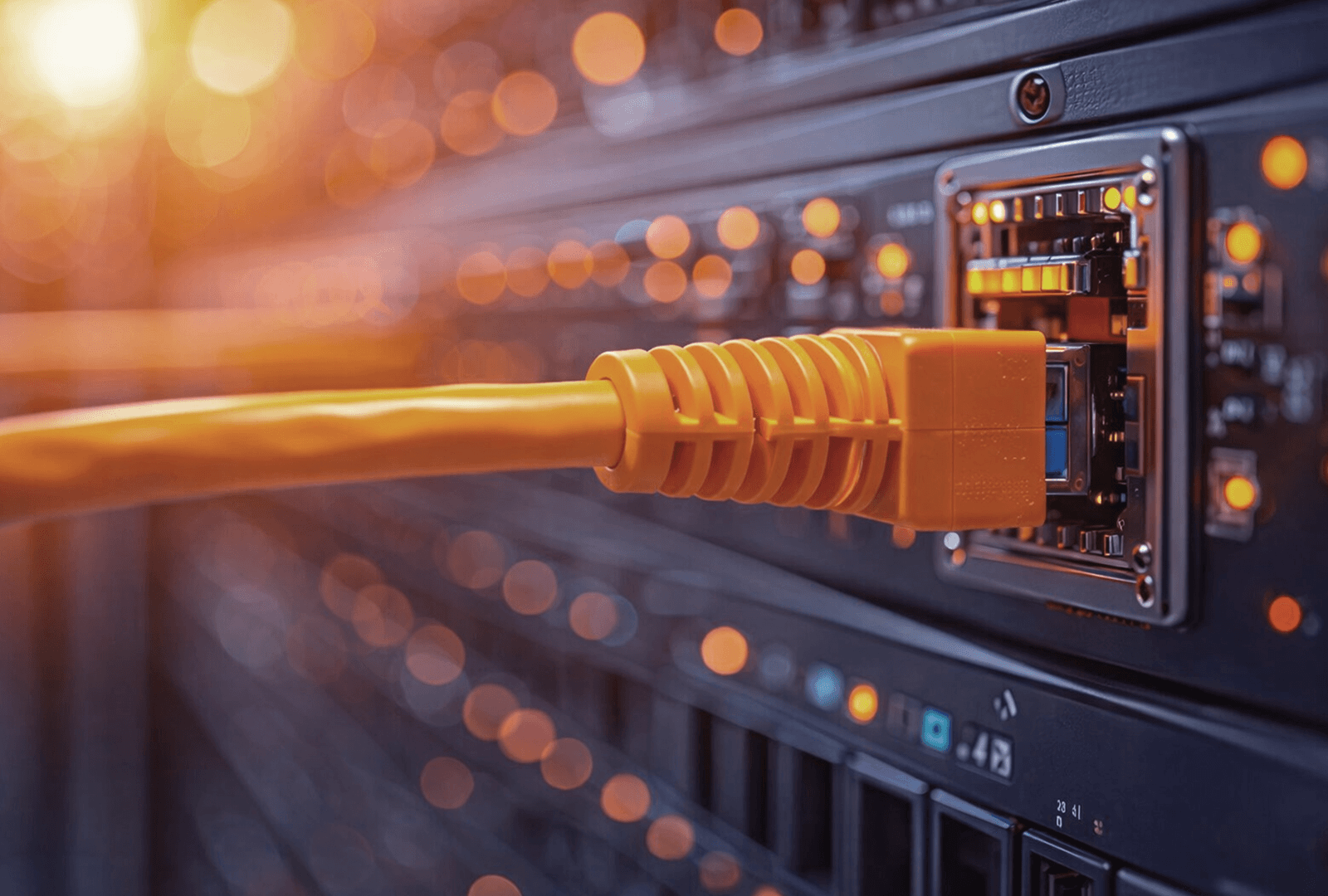
Born Electronics delivers high-performance networking solutions including PoE switches, industrial switches, and fiber connectivity products. Our technology is designed to ensure seamless connectivity, scalability, and long-term reliability for enterprises, surveillance systems, and smart infrastructure across industries.
Years Experience
Products
Global Clients
Projects
Why Choose Born Electronics

Designed for CCTV, Wi-Fi, and industrial environments, our switches ensure stable performance, efficient power delivery, and uninterrupted connectivity.

From enterprise networks to smart infrastructure, our solutions are built to scale, ensuring long-term reliability and seamless network expansion.
Network Reliability
Born Electronics stands out through its focus on innovation, durability, and user-centric design. Our products are built with advanced technology to ensure high performance, energy efficiency, and long-lasting reliability. With seamless connectivity, modern aesthetics, and strict quality control standards, we deliver electronics that are both functional and future-ready. Every feature is crafted to simplify usage, enhance productivity, and provide a superior user experience.

Why Choose Us
Get Started

We at Born Electronics ensure that all materials and products meet premium quality standards before delivery.
Premium-grade materials
Strict quality control
Reliable performance
Tested before delivery
Our products are designed to perform efficiently in different environments and conditions.
Climate-ready design
User-friendly operation
Adaptive technology
Smooth performance
We offer competitive pricing to ensure maximum value without compromising quality.
Best market pricing
High value products
Cost-effective solutions
Budget-friendly options
We provide strong after-sales support to ensure long-term customer satisfaction.
24/7 customer assistance
Quick issue resolution
Technical guidance
Long-term support
Our Solutions
Explore All
Testimonials

Healthcare Company
I get excellent support from the team handling my account, and the response that I get is excellent. Most of the time I get a response in 2 hrs despite the geographic and time difference; that’s amazing speed
Construction Company
I wanted to say thank you for the amazing experience that Born Electronics has provided. We are truly fortunate to have found such an incredible business partner.Thanks to all.
Networking Company
We worked with a Born Switches technician on our network configuration and this individual provided great customer service and went above and beyond to get our redundant configuration working properly.
115 London Road, Morden, England, SM4 5HP
info@bornelectronics.com
+44 7859 571344
Get the latest updates on networking solutions, products, and innovations.
© 2019 Born Electronics. All Rights Reserved.